![]()
![]()
Preparations
Tools: #2 Phillips screwdriver, small flathead screwdriver
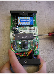
You will need a #2 Phillips head screwdriver to remove the back cover of the Gizmo. Place the Gizmo keyboard side down on a clean and soft work surface. Remove the two black 10-32 phillips screws. The back cover will now easily slip apart from the front portion of the Gizmo.
You will need a small flathead screwdriver to pry up the 40-pin PIC chip from its socket. Take precaution against electrostatic shock to the circuit board and PIC chip by grounding yourself before handling them. The most convenient way to dissipate static charge is to touch the metal frame of a grounded appliance, then do not walk around while handling the GIZMO or the PIC microprocessor.
|
Step 1: Remove the old PIC Locate the old PIC on the circuit board. Insert the tip of a small flathead screwdriver in the spacing between the PIC and its socket. Avoid making any contact with the other components on the board. Pry the chip upward gently as you insert the screwdriver, keeping the PIC level as it is raised from the socket. If the screwdriver is too wide, such that fully inserting it between the PIC and the socket would make contact with the pins, insert the screwdriver only partially and pry up one end of the chip slightly, then pry up the other end of the PIC. Repeat this process, keeping the chip level as it is raised. Avoid damaging the old PIC so that it can be used again, store the removed PIC in an anti-static container. |
 |
Step 2: Install the new PIC
Grasp the new PIC by its ends (try not to touch the pins) and remove it from its holder. Note that the notch on top of the chip should point toward the notch drawn on the silk screen of the circuit board. The pins of the chip are pre-loaded (spread wider than the separation between the rows of pinholes) to assure that they will make good contact when the chip is seated. Thus, you cannot insert the PIC if it is level with the socket.
Tilt the PIC sideways and place one row of pins into one side of the socket so that the pins are resting at the top of their respective pinholes, then tilt the PIC toward the socket until the other row of pins makes contact with the top of the holes. The tops of the holes are angled so that the pins will be guided inward as gentle pressure is applied. However, before applying pressure make sure that all the pins are indeed aligned, and that they are not hanging over the edges of the socket. If the pins are spread too wide, prod each pin gently into place with the screwdriver as you press the PIC into the socket. Note that when the PIC is fully inserted, a tiny gap will remain between the bottom of the PIC and the socket.
If you have any questions please give us a call toll free 1-888-436-9512.
Doug Fleenor Design
396 Corbett Canyon Road
Arroyo Grande, CA 93420
(805) 481-9599